Arcade Controller
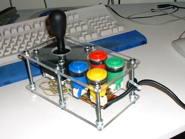
assembled arcade controller
NOTICE: This information is provided as is without any express or implied warranties. While effort has been taken to ensure the accuracy of the information contained in this text, the authors/maintainers/contributors assume no responsibility for errors or omissions, or for damages resulting from the use of the information contained herein. The contents of the information below might be totally inaccurate, inappropriate, or misguided. There is no guarantee as to the suitability of said information for any purpose.
Warning! The following are instructions for building a PC compatible arcade style game controller. I have put a lot of effort into ensuring that the information is accurate and to the best of my knowledge compatible with most PCs. However, I don't take any responsibility in case you follow these instructions and break your PC! You have been warned!
Theory
The standard 15 pin PC game port provides only 4 analog inputs and 4 digital inputs. The 4 analog inputs were intended to connect to 2 analog joysticks and the digital inputs were intended to connect to a total of 4 buttons, 2 to be used with each joystick. 5V is provided from the PC to power the controller.
The analog inputs were generally connected to potentiometers. These provided a large range of movement yet usually had a lot of temperature and motion related drift (requiring constant calibration). One potentiometer was used for each axis. Depending on the position of the 'stick' attached to the potentiometer, a signal was produced from 5V being applied to the varying resistance of the potentiometer's terminals.
An alternative way to detect the X and Y position of a stick is to scrap the potentiometer and only send one of a few discrete values. The values used emulated the far left (or top), centered and far right (or bottom) deflections of the potentiometer based values, and are 0 ohms, 50 kiloohms and 100 kiloohms (approximately), respectively. With both X and Y inputs combined together we get a matrix of 9 possible positions, allowing up to 8 different directions:
x = 0 k      x = 50 k     x = 100 k
y = 0 k      y = 0 k      y = 0 k

x = 0 k      x = 50 k     x = 100 k
y = 50 k     y = 50 k     y = 50 k

x = 0 k      x = 50 k     x = 100 k
y = 100 k    y = 100 k    y = 100 k
There were many commercial controllers that used this technology, of which the most popular had to be the 'Gravis Gamepad'. PC controllers of this genre were often referred to as 'gamepads', or as 'digital' joysticks since they did not utilize analog components such as potentiometers (however, they are still sending analog signals, yet only in discrete steps).
My arcade controller implementation uses real arcade components. The joystick contains separate microswitches for left, right, up and down directions. By combining multiple directions together the PC can detect 8 directions (for example, if both left and down were detected the PC would infer the 'down-left' direction).
Design
The following is the schematic that can be used to connect up the joystick and buttons to the 15 pin connector cable. Click it to see a detailed view.
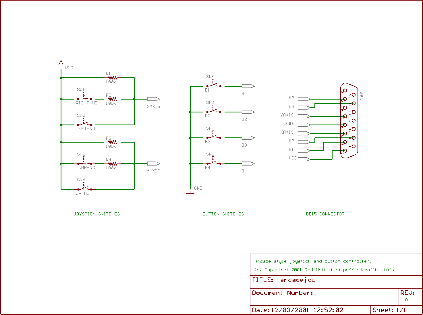
arcade controller schematic
I have also made the following versions of the schematic available:
The schematic was created with
Cadsoft's Eagle. Eagle is a very powerful and easy to use schematic capture, board layout and autorouter program that is available for the PC under Windows and Linux.
Parts
The joystick and the buttons I used can be obtained from
Happ Controls, or other arcade supply stores. I chose the Happ 'super joystick' and 'competition buttons', however any 4/8 direction joystick and set of 4 momentary push buttons should work. Keep in mind that whatever joystick you decide to use must have both 'NC' (normally closed) and 'NO' (normally open) contacts for each microswitch.
To connect the controller to the PC I bought a game port extension cable and wired up the board to the non-PC end of the cable.
The simplicity of the circuit means that a perfboard is more than adequate. Others may wish to make a PCB (feel free to use the
Eagle schematic file I created as a source for the board file).
What you use for a case is totally up to you. I chose to go with Plexiglass since it's cheap and looks great. However, cutting Plexiglass by hand requires a lot of work and produces toxic fumes. It's therefore wise to pay a little more to have the pieces cut to your specifications. I was fortunate/unfortunate to get a really good deal on my boards since the tech that did the cutting added a few extra holes to the bottom board (not on the specs!).
Construction
The first step was to wire up and solder the perfboard, as can be seen in the following image. Make sure the leads from the perfboard are long enough to allow the perfboard to be located anywhere inside the case, otherwise you may encounter difficulty when you put your creation together.
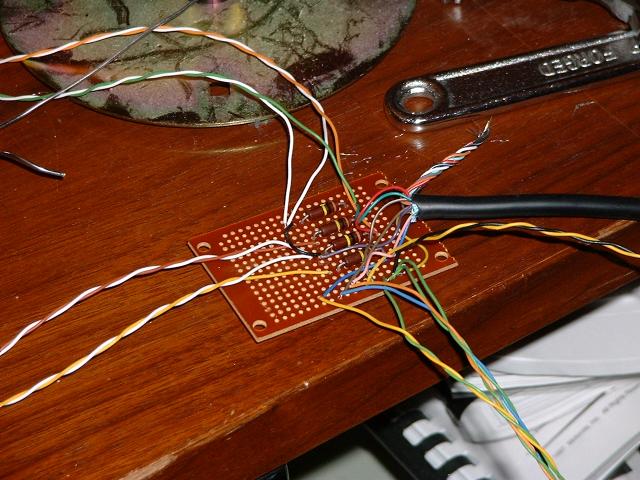
perfboard wired up
Next the joystick and buttons were installed on the upper Plexiglass board.
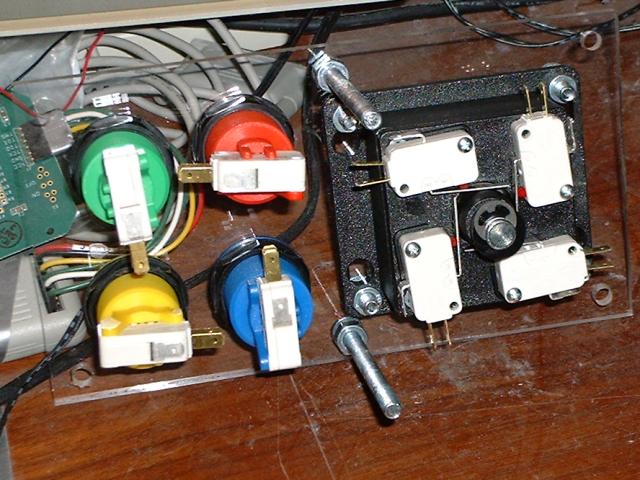
joystick and buttons installed
The wire leads from the perfboard were then soldered to the solder tail tabs of the joystick and buttons.
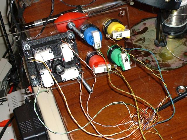
connecting the wires
Before attaching the perfboard to the bottom Plexiglass board I tested the controller on a PC.
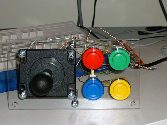
testing it out
The perfboard was then attached to the bottom Plexiglass board using double sided tape. The upper and lower Plexiglass boards were fixed together using 1/4" bolts. Yes, the controller in this image has the joystick on the left side - no I am not left handed, yet I prefer to have the joystick on the left side!
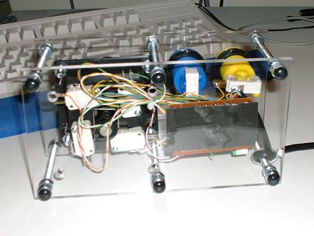
bottom view
The final step is to download
MAME and play some arcade games using your new controller. Enjoy!
