Micro Programmed Arithmetic Processor
My
Electrical Engineering fourth year project was the design of a 'Micro Programmed Arithmetic Processor' capable of division and multiplication, for the project course ELG4905 in the winter semester of 1995. Professor Krieger asked me to build the micro programmed processor in order to demonstrate the capabilities of such a device to the students of ELG2181. Part of the students' laboratory will be devoted to experimenting with the hardware implementation which I created.
There is a Detailed Design (DD) document for the project available in
postscript and
PDF formats.
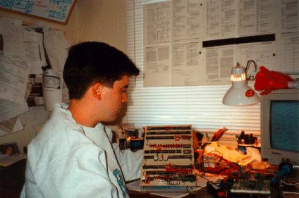
The following is a picture of me with my logic probe during the construction phase of this project.
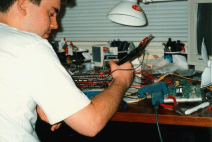
Me and my logic probe
The device is a digital trainer that will allow the students of ELG2181 to experiment with a micro programmed processor. The trainer demonstrates the potential of the micro programmed processor showing how such a device would be designed to execute not only simple functions such as add and subtract, yet also much more complex ones such as multiply and divide.
I designed it to be able to act as a 'math coprocessor' which will execute an operation and flag the main processor when the requested instruction has completed.
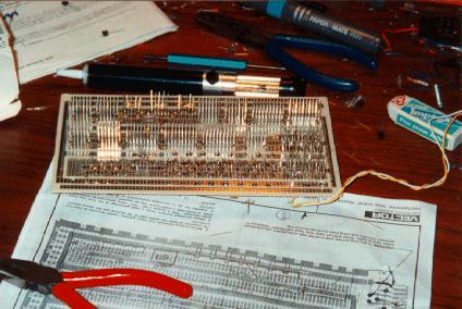
The second board before wire wrapping
This is the bottom view of the second board just before wire wrapping. The LEDs and switches were added first, then the sockets were soldered to the board. The next step was to connect the pins together using wire wrap.
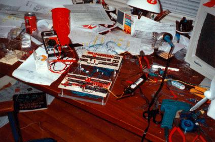
Integrating the boards together
Luckily I had a wire wrap power tool to assist me, which can be seen in the bottom right corner of this picture. Thanks go out to our lab tech Mitch for lending it to me. Otherwise it would have taken many times longer using the hand tool. Of course this would still have been a hundred times faster than attempting to connect it with just solder and wire!
The trainer was implemented using 55 TTL chips and used over one hundred square inches of proto board. The design was simulated using
Beige Bag's 'B2Logic 3.0' digital simulation software.
Some of the features of the processor include:
- accumulator register
- 'built-from-scratch' 4-bit ALU
- status register
- 256 by 16 bit capable microcode
- able to execute both multiply and divide
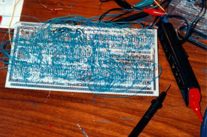
The first board after being wire wrapped
This picture shows the completed wire wrap connections for the first board. There are over 500 connections for this board and around 2000 for the entire project.
Yes, that's me holding my completed baby!
This is me holding the completed hardware implementation. You can see more detail in the next photo.
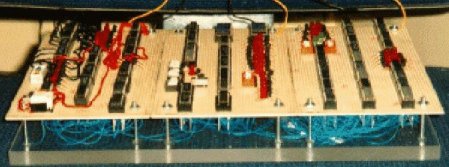
Side profile of the finished product
This picture shows the side profile of the trainer. The left side of the picture shows where the student would operate the clock and instruction inputs (dip switches). There are various LEDs and switches throughout. A half inch thick piece of plexiglass was used as a base for the boards. Hopefully this will provide some shock absorption in case it is dropped.
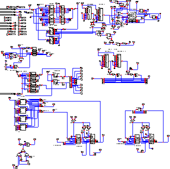
High level view of the complete schemetic
To print out the entire design requires nearly 40 pages (12 just for the 4 bit ALU!). Here is a 'compressed' view (without the detailed ALU).
I also designed a
Windows based GUI simulator which gives students the ability to work with the trainer without the need to go into the lab. It is available for
download. Uncompress the zip file and then run
setup.exe in Windows (3.x, 95 and 98). It will create a directory and a program group automatically. It provides a GUI that looks just like the hardware version, even with switches and colourful LEDs!
There is a user manual for the simulator available in
postscript and
PDF formats.
