FreeCore Function #5:
I2C
Controller
Module name:
I2C
Current release: version 3.0, January 29,
1998
Contributed by: Rune Baeverrud
Changes since version 2.0
Changes since version 1.0
Clock speed and resource usage in I2C Controller version 3.0
I compiled this with with the following options:
Achieved results:
Description
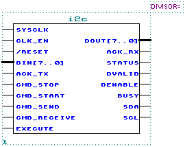
Shown below is the I2C ("I squared C") controller module.

The controller has the following key features:
You will probably find that this controller is stable and very easy to use.
| PARAMETERS | |
| DIVISOR | The DIVISOR value should be set to ((the input frequency on clk_en) / (400kHz)). For instance: If your system clock frequency is 50MHz, and you use the div_by_n module externally to generate a 10MHz clock enable signal, you could apply this 10MHz signal to clk_en. You should then set the divisor value to 10MHz / 400kHz = 25. This would be equivalent to using a 10MHz system clock frequency and tie clk_en to VCC. |
| INPUT PORTS | |
| SysClk | System clock input. |
| clk_en | Clock Enable input. Can be tied to VCC if using an appropriate DIVISOR parameter value. |
| /reset | Asynchronous reset of all registers within the I2C Controller. |
| Din[7..0] | Parallel data input. |
| Ack_Tx | Acknowledge to send, when in receiver mode. |
| Cmd_Stop | Generate STOP condition on I2C port. |
| Cmd_Start | Generate START condition and send slave address on I2C port. |
| Cmd_Send | Send a byte to I2C port. |
| Cmd_Receive | Receive a byte from I2C port. |
| Execute | After Execute goes to logic high then on the next positive edge of SysClk, Din[], Ack_Tx, Cmd_Stop, Cmd_Start, Cmd_Send, Cmd_Receive will be sampled, and execution will start. |
| OUTPUT PORTS | |
| Dout[7..0] | Parallel data output. Always reflects the internal transmission shift register, so it's value is not always valid. |
| Ack_Rx | Last received acknowledge. |
| Status | I2C bus has been claimed. Logic high between START and STOP conditions. |
| DValid | Logic high when Dout[] is valid. Goes active immediately after the acknowledge bit has been transferred. |
| DEnable | Like DValid, but remains high for one system clock (SysClk) period only. |
| Busy | While Busy is high, no new commands are accepted. In fact, Execute has to go low for Busy to go low, so that new commands can be accepted. |
| SDA | I2C data |
| SCL | I2C clock |
Output signals DValid, DEnable, Ack_Rx and Dout[] are also active during send mode, so these signals may be used for implementing the logic or microprocessor interface. When in send mode, the sent data will also be received at the same time.
The Busy output must be low when the Execute input is pulled high, or else the command will not be accepted. The Busy output will remain high as long as Execute remains high or a command is in execution.
When Busy is low, and Execute goes high, then on the next SysClk rising edge the Din[], Ack_Tx, Cmd_Stop, Cmd_Start, Cmd_Send, Cmd_Receive will be sampled. Only one of of the Cmd_* lines are allowed to be logic high, or else the operation of the controller will be unpredictable. The value of Ack_Tx is only meaningful if the Cmd_Receive command is issued.
When using the I2C module in a MAX device, you will need to issue a stop condition as the first command after a system reset, for the SDA and SCL lines to go high impedance (external pull-up) state. This is not necessary in a FLEX device. The reason for this is that inverted outputs are unsupported in MAX, so a NOT gate pushback occurs during compilation for these devices.
| INSTRUCTION | DESCRIPTION |
| Cmd_Start | Generates a START condition on the I2C port, and continues to send the byte loaded on the Din[] input port. The value of the Din[] port should therefore be the correct slave address with the R/W bit set accordingly. This command will automatically generate a repeated start condition if the I2C bus was already claimed and a Cmd_Stop command was not issued prior to Cmd_Start. |
| Cmd_Stop | Generates a STOP condition on the I2C port. |
| Cmd_Send | Send data from the Din[] input port to the I2C port. |
| Cmd_Receive | Receive a byte from the I2C port and present it on the Dout[] port. |
Simulations
In the simulations below I've only been interested in simulating different physical conditions, and higher level protocols determining what is a slave address, data byte, R/W bit and so on is of no interest here. For more information on the I2C standard and how to use it, I suggest you download the Philips application note "The I2C-bus and how to use it" (3114.PDF) from the Philips web site. Last time I checked - I found it at this web address: http://www-us.semiconductors.philips.com/cgi-bin/searchcat?cat=3999&code=16
The following section will hopefully clarify any question you might have about the functionality of the I2C Controller core. I suggest you download the I2C.SCF file - which you can open in the MAX+PLUS II Waveform Editor. Alternatively, you can look at the simulation in the images below. To download the I2C.SCF file, click
Please be aware that simulation of an external pull-up bus like the I2C bus is very difficult with MAX+PLUS II. If you try to change anything in the simulation file - you must first run one simulation, and then fix the bus contention errors by setting the SDA and SCL inputs (NOT the SDA and SCL outputs) to appropriate high, low or tristate values. This is very tedious. The reason for this diffuculty is that you cannot define an input to be weak high - like you would with an external pull-up resistor. Instead you must impose a tristate on the input when the output is driving low, and impose a high or low on the input when the output is not driving low.
This is how the the SDA and SCL ports really looks like when compiling for a physical device target:

The reason for the inverters before and after the register, is that the device powers up with all registers cleared. By doing it this way, the I2C bus will power up with both SDA and SCL high.
When compiling for a simulation target, the SDA and SCL ports looks like this, easing simulation tremendously:
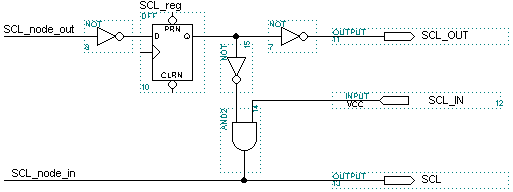
When compiling for a simulation target, there is also two additional output signals available:
Simulation File Description
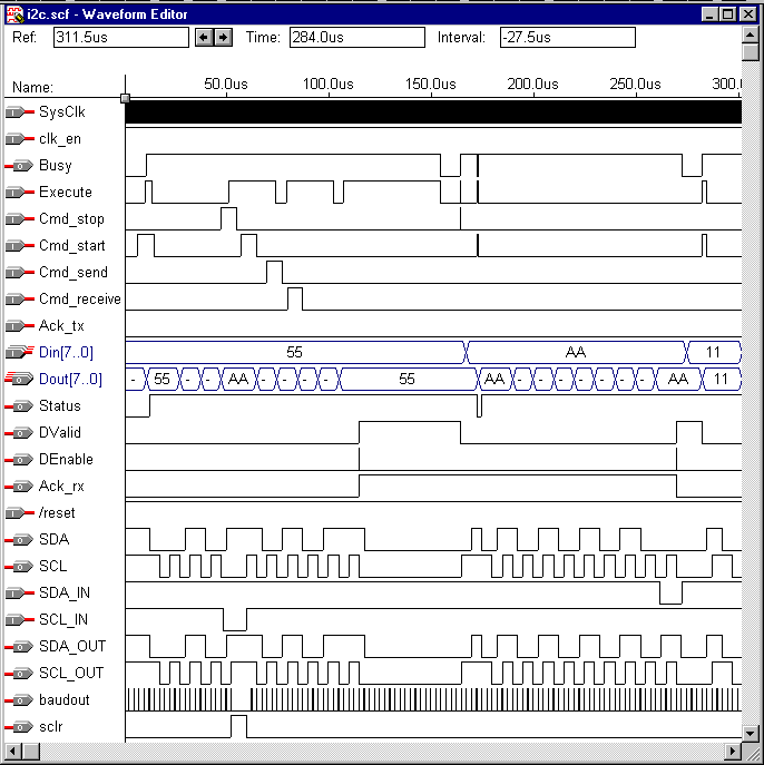
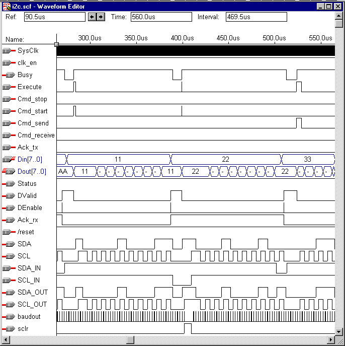
Please note that the simulations below has been performed using functional simulation only, so they should be easy to recreate.
| TIME | EVENT |
| 0.0us | I2C bus is idle. |
| 10.8us | Execute goes high. All other inputs must be stable at this time. A start command is given. H55 is present at the Din[] input, to be sent onto the I2C bus immediately after the start condition. |
| 10.9us | All inputs are sampled at the first SysClk edge. Busy goes high, meaning no more commands will be accepted until Busy goes low again. |
| 12.6us | Status goes high indicating that the I2C bus has been claimed by the I2C controller. |
| 12.6 17.6us | The start condition is presented on the I2C bus. |
| 20.1 107.6us | H55 is sent onto the I2C bus |
| 27.6 105.1us | SDA is sampled on the falling edge of SCL, in both send and receive modes. You can see this on Dout[] which always reflects the current value of the transmission shift register. When you send data, you should be receiving the data you send at the same time. At 105.0us you can see that H55 has been received or read back from the I2C bus into the I2C controller. This could be a good debugging tool when your I2C bus does not behave like expected. |
| 48.5 60.0us | The slave is forcing wait states by pulling SCL low. |
| 47.5 102.5us | Various activity on Execute, Cmd_stop, Cmd_start, Cmd_send or Cmd_receive have absolutely no effect while Busy is high. |
| 115.1us | The acknowledge bit present on the I2C bus is sampled, and the value sampled on SDA will immediately be available on the Ack_rx line. DValid goes high indicating that valid data is present at the Dout[] output. DEnable goes high for one system clock period very useful for interfacing to external interface logic, generating interrupts, etc. |
| 155.0us | Execute is taken low. It is not necessary to keep Execute high for long periods of time. It is only necessary to pulse Execute high long enough for it to be sampled on the next system clock (SysClk) pulse. In this case with a SysClk frequency of 10MHz a 100ns pulse would be more than sufficient. |
| 155.1us | Busy goes low. Busy will not go low until both these
conditions are met:
In this case - the high state of Execute forced Busy to remain high after the instruction itself had finished execution. If Execute had been taken low before the instruction itself had finished, Busy would have gone low at 117.6us. |
| 164.4us | The stop command is given. |
| 164.5us | Busy goes high. DValid goes low indicating that data present at the Dout[] output is no longer valid. |
| 172.6us | Status goes low the I2C bus is now free. |
| 173.0us | The start command is given, and HAA at the Din[] input will be sent onto the I2C bus. |
| 173.1us | Inputs are sampled and Busy goes high. |
| 175.1us | Status goes high again indicating that the I2C bus has been claimed. |
| 175.1 180.1us | The start condition is presented on the I2C bus. |
| 182.6 262.6us | HAA is transmitted on the I2C bus. |
| 270.1us | The acknowledge bit present on the I2C bus is sampled, and Dout[], Ack_rx, DValid and DEnable will all be valid. |
| 282.5us | Another start command is given without first supplying a stop command. |
| 292.6 297.6us | Since no stop command was given a repeated start condition is presented on the I2C bus, and H11 will be sent on the I2C bus. |
| 390.0 410.0us | The slave device is forcing SCL low. |
| 399.6us | Yet another start command is given without first issuing a stop command. |
| 415.1 420.1us | The repeated start condition is presented on the I2C bus, but is being delayed by the slave forcing SCL low. |
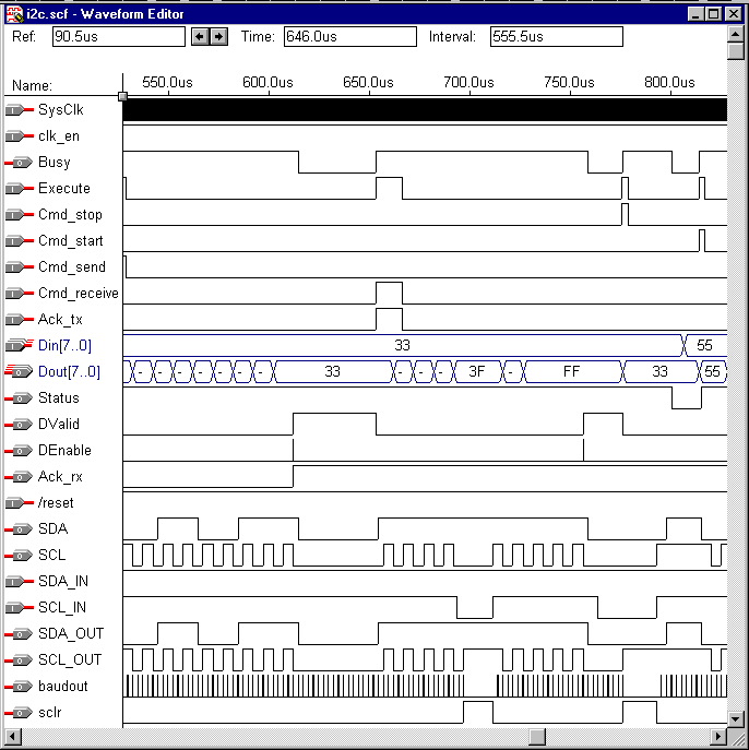
| 524.0us | A Send command is given, and H33 will be sent onto the I2C bus. |
| 654.0us | A receive command is given. This time it is important to set the value of the Ack_tx input before issuing the command! This value will be the I2C acknowledge from the I2C controller to the slave after the data has been received from the slave on the I2C bus. |
| 694.0 712.0us | The slave is slowing down the I2C bus (forcing wait states) by pulling SCL low. |
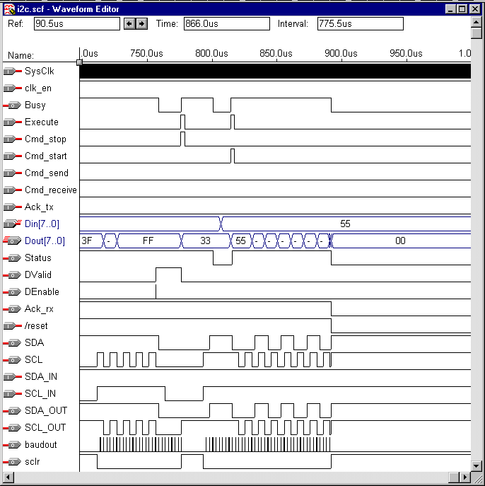
| 764.5 793.5us | The slave is slowing down the I2C bus (forcing wait states) by pulling SCL low. |
| 776.5us | A Stop command is given, but the execution is delayed caused by the slave forcing SCL low. |
| 793.5 798.6us | The stop condition is presented onto the I2C bus. |
| 815.0us | Another Start Command is given, and H55 is scheduled to be sent onto the I2C bus. |
| 880.0us | /reset goes low all registers are cleared and all activity is reset to a known default state. |
Simulation 0.0 - 300.0us:
Simulation 250.0 - 550.0us:
Simulation 500.0 - 800.0us:
Simulation 700.0 - 1000.0us:
![]()
Last updated 08 Feb 2001 11:53