FreeCore
Library
Albert Lindmeier's Prototyping Board for FLEX
8000 Devices
This guy works as a Field Applications Engineer within Altera, so obviously he must be knowing what he is doing!
I've not testet this board myself, but here is some key information from the designer himself:
![]()
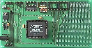
The main purpose of this FLEX 8000 prototyping board is to enable the user to do fast prototyping of his design. Designs for FLEX 8000 can be easily downloaded to the board and verified. The user can add circuitry on the prototyping aerea of the board and connect it to the FLEX.
The FLEX 8000 prototyping board supports the EPF8282(A)LC84, EPF8452(A)LC84 and the EPF8636(A)LC84. All of the FLEX 8000 pins are easily accessible through test points around the chip.
In addition to a connector for the BitBlaster or ByteBlaster for passive serial configuration the board also contains a 8-pin-socket for the serial configuration EPROM (EPC1, EPC1064, EPC1213) and a 28-pin-socket for a parallel configuration EPROM (Any standard EPROM of proper size, e.g. 27256). The different configuration modes can be selected by DIP-switches.
Apart form configuration this parallel EPROM could also be used for example as a large parameter lookup-table, or it could be replaced by a RAM to add some user RAM-space to the FLEX (FIFO etc.).
There is also a 14-pin socket for a standard oscillator either in a rectangular (14-pin) package or in the smaller square package (8-pin). The output of the oscillator is shielded and feeds directly the dedicated input pin 12 of the FLEX. An additional clock termination network (R/C) can be added if required.
Two status LED’s on the board show the status of the device: a green LED is indicating the successful configuration (CONF_DONE) and a red one is indicating an error (nSTATUS). A debounced reboot-switch allows the reconfiguration of the chip when configured from an on-board serial or parallel EPROM.
JTAG is supported with the EPF8282 and EPF8636. There are two JTAG connectors on the board, one JTAG input and one JTAG output. Multiple boards can be cascaded by connecting the JTAG output from one device to the JTAG input of the next device. On the last board a jumper must be set to terminate the JTAG chain.
The full manual and ordering information can be found here. Albert Lindmeier can also be reached by email at alindmei@altera.com, but please be aware that this work is not Altera official.
![]()
Last updated 08 Feb 2001 12:25